
Service Manual auto radio tape PANASONIC CQ-C1300AN, C1300GN, C1400N
Service Manual auto radio tape PANASONIC CQ-C1300U
Service Manual auto radio tape PANASONIC CQ-C1301NE, C1311NE, C1321NE
Service Manual auto radio tape PANASONIC CQ-C1303NE
Service Manual auto radio tape PANASONIC CQ-C1333W
Schematic diagram auto radio tape PANASONIC CQ-C3300N
Schematic diagram auto radio tape PANASONIC CQ-C3301N
Service Manual auto radio tape PANASONIC CQ-C3401W
Schematic diagram auto radio tape PANASONIC CQ-C5300N, C5400N
Circuit diagram auto radio tape PANASONIC CQ-C5301N
Service Manual auto radio tape PANASONIC CQ-C5301W, C5401W
Service Manual auto radio tape PANASONIC CQ-C5303W, C5403W
Service Manual auto radio tape PANASONIC CQ-C7301N, C8301N, C8351N
Schematic diagram auto radio tape PANASONIC CQ-C9700N, C9800N
Service Manual auto radio tape PANASONIC CQ-C9701N, C9901N
CQ-D50LEEP
CQ-DF200
CQ-DF600
Service Manual auto radio tape PANASONIC CQ-DFX400N, DFX600N
Service Manual auto radio tape PANASONIC CQ-DFX572N
Schematic diagram auto radio tape PANASONIC CQ-DFX601N, DFX701N, DFX751N
Service Manual auto radio tape PANASONIC CQ-DFX802N
Service Manual auto radio tape PANASONIC CQ-DFX883U
Service Manual auto radio tape PANASONIC CQ-DFX888LEN, DFX777LEN
Schematic diagram auto radio tape PANASONIC CQ-DP153W
CQ-DP34LEEP
Service Manual auto radio tape PANASONIC CQ-DP383W, DP383WJ
Service Manual auto radio tape PANASONIC CQ-E03, E05
Schematic diagram auto radio tape PANASONIC CQ-ET8060A
CQ-FR320U
CQ-FX220
CQ-FX420
Schematic diagram auto radio tape PANASONIC CQ-FX220N, FX420N, FX620N
Circuit diagram auto radio tape PANASONIC CQ-FX323W
Service Manual auto radio tape PANASONIC CQ-FX44LEN, FX66LEN
Schematic diagram auto radio tape PANASONIC CQ-FX620U
Schematic diagram auto radio tape PANASONIC CQ-FX75LEN, FX95LEN
Service Manual auto radio tape PANASONIC CQ-HX2083N
Schematic diagram auto radio tape PANASONIC CQ-J03LEE
Service Manual auto radio tape PANASONIC CQ-JA1070L, JA1071L, JA1072L, JA1073L, JA1074L
Service Manual auto radio tape PANASONIC CQ-JA1920L, JA1924L
Service Manual auto radio tape PANASONIC CQ-JH8061Z, JH8062Z
Service Manual auto radio tape PANASONIC CQ-JS6910X, JT1010X
Service Manual auto radio tape PANASONIC CQ-JV1060L
Service Manual auto radio tape PANASONIC CQ-LA1923L
Schematic diagram auto radio tape PANASONIC CQ-R155EW
CQ-R215P
Schematic diagram auto radio tape PANASONIC CQ-R221W
CQ-R30LEEP
CQ-R30VEG/LEE/GLEE
CQ-R35VEG/LEE
CQ-RD40LEN
CQ-R45LEEP
CQ-R45LEN
Service Manual auto radio tape PANASONIC CQ-R805LEEP
Schematic diagram auto radio tape PANASONIC CQ-RD310LEN, RD320LEN
Schematic diagram auto radio tape PANASONIC CQ-RD313N, RD323N, RD333N
CQ-RD555
CQ-RD575
CQ-RD595LEN
Service Manual auto radio tape PANASONIC CQ-RDP200LEN, RDP210LEN
Service Manual auto radio tape PANASONIC CQ-RDP202N, RDP212N
Schematic diagram auto radio tape PANASONIC CQ-RDP472N
Schematic diagram auto radio tape Panasonic CQ-RDP700LEN, RDP750LEN
Service Manual autoradio tape PANASONIC CQ-RG131W
Service Manual autoradio tape PANASONIC CQ-RG133W1
Schematic diagram auto radio tape PANASONIC CQ-TS0920A
Selasa, 22 April 2008
Schematic diagrams auto radio tape PANASONIC
Senin, 21 April 2008
Schematic diagrams auto radio tape LG
Service Manual auto radio tape LAC-M0510R
Schematic diagram auto radio tape LG LAC-M1500, M2500
Service Manual auto radio tape LG LAC-M1501
Service Manual auto radio tape LG LAC-M4510
Schematic diagram auto radio tape LG LAC-M8410R
Service Manual auto radio tape LG LAD-4600R
Schematic diagram auto radio tape LG TCC-570
Schematic diagram auto radio tape LG TCC-572, 670, 672
Circuit diagram auto radio tape LG TCC-583
TCC-2010
TCC-2510
Schematic diagram auto radio tape LG TCC-5610, 5620, 5630, 5650
Schematic diagram auto radio tape LG TCC-5710, 5720
Schematic diagram auto radio tape LG TCC-6210, 6220, 6230
Service Manual auto radio tape LG TCC-6430
Schematic diagram auto radio tape LG TCC-8010
Circuit diagram auto radio tape LG TCC-9010
Schema auto radio tape LG TCC-9210
Schematic diagram auto radio tape LG TCC-9310
Schematic diagram auto radio tape LG TCC-9410
Schematic diagram auto radio tape LG TCC-9420
Service Manual auto radio tape LG TCC-9510
Schema auto radio tape LG TCC-9610
Circuit diagram auto radio tape LG TCCH-100
Schematic diagram auto radio tape LG TCH-70
Schema auto radio tape LG TCH-500
Schematic diagram auto radio tape LG TCH 600
Service Manual auto radio tape LG TCH-800
Schematic diagram auto radio tape LG TCH-M550
Service Manual auto radio tape LG TCH-M900
Minggu, 20 April 2008
Schematic diagrams auto radio tape KENWOOD
Service Manual automobile DVD a receiver with the monitor KENWOOD DDX6027, 6027Y, 7017, 7037, 7047, 7067
Service Manual auto radio tape KENWOOD DPX-3030, MP4030
Service Manual the automobile amplifier KENWOOD KAC-529S
The scheme of the automobile amplifier KENWOOD KAC-821
Schematic diagram auto radio tape KENWOOD KDC-1016, 115S
Service Manual auto radio tape KENWOOD KDC-2016, 215S, 35MR
Service Manual auto radio tape KENWOOD KDC-2019, 217, 219, 29MR, 3020, 4020
Schematic diagram auto radio tape KENWOOD KDC-2021S
Service Manual auto radio tape KENWOOD KDC-2023, 2024, 2094, 222, 3023
Service Manual auto radio tape KENWOOD KDC-205, 205CR, 226, 2026, 3026, 3026R
Service Manual auto radio tape KENWOOD KDC-3022, 322, 5023R, 5024, 507, 5094RY
Service Manual auto radio tape KENWOOD KDC-3024, 307
Service Manual auto radio tape KENWOOD KDC-3028, 328
Service Manual auto radio tape KENWOOD KDC-3031, 309, F331
Service Manual auto radio tape KENWOOD KDC-315S, 415S, 4015, 4016
Service Manual auto radio tape KENWOOD KDC-4070
Service Manual auto radio tape KENWOOD KDC-4590R,V,Y,YV
Service Manual auto radio tape KENWOOD KDC-5019, 519, 7021, 7021Y, 8020, B7021
Service Manual auto radio tape KENWOOD KDC-5060R
Schematic diagram auto radio tape KENWOOD KDC-7040R, 8040R
Schematic diagram auto radio tape KENWOOD KDC-7080R
Service Manual auto radio tape KENWOOD KDC-7090R
Service Manual auto radio tape KENWOOD KDC-715S, 8015, 8016
Service Manual auto radio tape KENWOOD KDC-719, X559, Z638, Z737
Service Manual auto radio tape KENWOOD KDC-8021, M9021, X859
Service Manual auto radio tape KENWOOD KDC-8026, MP825, MPV8025, W7027
Service Manual auto radio tape KENWOOD KDC-9023R, PSW9524, X969
Schematic diagram auto radio tape KENWOOD KDC-93R
Service Manual CD Changer KENWOOD KDC-C715
Service Manual auto radio tape KENWOOD KDC-M6021
Service Manual auto radio tape KENWOOD KDC-M6024, MP522, X569
Service Manual auto radio tape KENWOOD KDC-M7024, MP822
Service Manual auto radio tape KENWOOD KDC-MP202, MP333RC, MP433
Service Manual auto radio tape KENWOOD KDC-MP2028, MP228, MP3029, MP4029
Service Manual auto radio tape KENWOOD KDC-MP222, MP4023
Service Manual auto radio tape KENWOOD KDC-MP225, MP4026, W427Y, W4527
Service Manual auto radio tape KENWOOD KDC-MP332, MP5033, W534, W534Y
Service Manual auto radio tape KENWOOD KDC-MP4028, MP428, MP6029
Service Manual auto radio tape KENWOOD KDC-MP425, MP6026, W6027
Service Manual auto radio tape KENWOOD KDC-MP5029, W5031, W5031Y, W531Y
Service Manual auto radio tape KENWOOD KDC-MP6025, MP625, MP858, W6527, W6527Y
Service Manual auto radio tape KENWOOD KDC-MP628, MP7028, MP728, MP8029, W7031/Y
Service Manual auto radio tape KENWOOD KDC-MP819, X659, Z838
Service Manual auto radio tape KENWOOD KDC-MP925, W8027
Service Manual auto radio tape KENWOOD KDC-PS9016R, PS9080R, X815, X915
Service Manual auto radio tape KENWOOD KDC-W237AY/GY, W3037AY/GY, W311AY/GY, W3537AY/GY, W4037Y
Service Manual auto radio tape KENWOOD KDC-W4031, W409, W431, W4531, WF431
Schematic diagram auto radio tape KENWOOD KDC-W40GY, W434A, W434G, W434GY
Service Manual auto radio tape KENWOOD KDC-W6531, X589, X7529
Schematic diagram auto radio tape Kenwood KDC-W707, W707Y
Service Manual auto radio tape KENWOOD KDC-X959, Z738, Z838W, Z939
Service Manual auto radio tape KENWOOD KDC-Z727, Z727
Service Manual auto radio tape KENWOOD KMD-PS971R, X92
Schematic diagram auto radio tape KENWOOD KRC-11R, 152L, 159R
Service Manual auto radio tape KENWOOD KRC-13RG, 178R, 23R, 278R, 280RG
Service manual auto radio tape KENWOOD KRC-15RG, 179R, 25R, 279R, 281RG
Service Manual auto radio tape KENWOOD KRC-208S, 218, 268, 288, 28MR
Service Manual auto radio tape KENWOOD KRC-225, 235, 265
Schematic diagram auto radio tape KENWOOD KRC-29Y, 35R, 379R, 479R, 481R
Schematic diagram auto radio tape KENWOOD KRC-30Y, 36, 391
Service Manual auto radio tape KENWOOD KRC-31Y, 36, 366L, 37, 391, 394, 466R, 4904Y
Service Manual auto radio tape KENWOOD KRC-477R, 477RY
Service Manual auto radio tape KENWOOD KRC-559R, 585, S505
Service Manual auto radio tape KENWOOD KRC-578R, 680R
Service Manual auto radio tape KENWOOD KRC-605, 659R, 685R, PS655
Schematic diagram auto radio tape KENWOOD KRC-607, 6701RY, 687x, X657
Service Manual auto radio tape KENWOOD KRC-608, 678R
Schematic diagram auto radio tape KENWOOD KRC-655R
Service Manual auto radio tape KENWOOD KRC-705, 759R/RY, 785, 805, 859C/CY/R/RY/W/WY, 885W, PS955
Service Manual auto radio tape KENWOOD KRC-708, 888, PS988R, X858
Service Manual auto radio tape KENWOOD KRC-709, 779R, 779RY, 889
Schematic diagram auto radio tape KENWOOD KRC-758R, 803, 858R, 883W, 903, 953, 958R, 993
Service Manual auto radio tape KENWOOD KRC-778R, 878R, PS978R
Service Manual auto radio tape KENWOOD KRC-V679R
Sabtu, 19 April 2008
Schematic diagrams auto radio tape JVC
Service Manual auto radio tape JVC KD-AR270, G220, G227, G321, G322, G323, G324, G325, G326, G327
Schematic diagram auto radio tape JVC KD-AR370J, G320J, G421E, G424UI, G425U, G427EE
Service Manual auto radio tape JVC KD-AR470, G420, G521, G524, G525, G527
Service Manual auto radio tape JVC KD-AR870J, G820J, G821Ex, G824UI, G825Ux, G827EE
Service Manual auto radio tape JVC KD-AVX1
Service Manual auto radio tape JVC KD-AVX2
Service Manual auto radio tape JVC KD-DV4200, DV4201, DV4202, DV4203, DV4204, DV4205, DV4206, DV4207
Service Manual auto radio tape JVC KD-DV5000
Service Manual auto radio tape JVC KD-DV5101
Service Manual auto radio tape JVC KD-G111, G117
Service Manual auto radio tape JVC KD-G201, G202, G207
Service Manual auto radio tape JVC KD-G311, G312, G317
Schematic diagram auto radio tape JVC KD-G317EE, G417EE
Схемы автомагнитолы JVC KD-G331, G332, G333, G334, G335, G337, G338
Schematic diagram auto radio tape JVC KD-G405, G455
Schematic diagram auto radio tape JVC KD-G407
Schematic diagram auto radio tape JVC KD-G415, G416
Schematic diagram auto radio tape JVC KD-G611, G612, G617
Schematic diagram auto radio tape JVC KD-G701
Service Manual auto radio tape JVC KD-G801, G807
Service Manual auto radio tape JVC KD-GS620
Service Manual auto radio tape JVC KD-GS920
Service Manual auto radio tape JVC KD-GT7
Schematic diagram auto radio tape JVC KD-LH1105
Schematic diagram auto radio tape JVC KD-LH911, LH917
Schematic diagram auto radio tape JVC KD-LHX501, LHX502
Schematic diagram auto radio tape JVC KD-LX10R, LX30R
Schematic diagram auto radio tape JVC KD-LX333R
Service Manual auto radio tape JVC KD-LX50R
Schematic diagram auto radio tape JVC KD-LX555R
Service Manual CD Changer JVC KD-MK88
Schematic diagram auto radio tape JVC KD-S5055
Service Manual auto radio tape JVC KD-S6060
Schematic diagram auto radio tape JVC KD-S611
Service Manual auto radio tape JVC KD-S621
Service Manual auto radio tape JVC KD-S653R, S656R
Service Manual auto radio tape JVC KD-S673R, S676R
Service Manual auto radio tape JVC KD-S700, S7250
Service Manual auto radio tape JVC KD-S707R, S737R, SX838R
Schematic diagram auto radio tape JVC KD-S847
Schematic diagram auto radio tape JVC KD-S891R
Schematic diagram auto radio tape JVC KD-SC601, SC607
Service Manual auto radio tape JVC KD-SC900R
Service Manual auto radio tape JVC KD-SH1000
Schematic diagram auto radio tape JVC KD-SH55, SH77
Service Manual auto radio tape JVC KD-SH909R
Service manual auto radio tape JVC KD-SH9101, SH9102, SH9103, SH9104
Schematic diagram auto radio tape JVC KD-SX921R, SX992R
Service Manual auto radio tape JVC KD-SX950
Service Manual auto radio tape JVC KD-SX997R, SX998R
Схема автомобильного усилителя JVC KS-AX5700
Service Manual auto radio tape JVC KS-F150, FX12
Service Manual auto radio tape JVC KS-F315
Schematic diagram auto radio tape JVC KS-F525
Circuit diagram auto radio tape JVC KS-F545
Schematic diagram auto radio tape JVC KS-FX185, FX385
Schematic diagram auto radio tape JVC KS-FX381
Service Manual auto radio tape JVC KS-FX815, FX915R
Service Manual auto radio tape JVC KS-LH6R
Schematic diagram auto radio tape JVC KS-LX200R
Service Manual auto radio tape JVC KS-RT424
Service Manual auto radio tape JVC KS-RT55
Service Manual auto radio tape JVC KS-RT626
Service Manual auto radio tape JVC KS-RX177
Schematic diagram auto radio tape JVC KW-XC939EE
Jumat, 18 April 2008
Schematic diagrams auto radio tape Grundig
Service Manual auto radio tape Grundig 5100RDS, 5101RDS, 5200RDS, 5201RDS
Service Manual auto radio tape Grundig 5300RDS, 5600RDS
Service Manual auto radio tape Grundig Allixx SCD5410
Service Manual auto radio tape Grundig EC4000RDS
EC4000
Service Manual auto radio tape Grundig EC4490CD
EC4600
Schematic diagram auto radio tape Grundig OPEL CAR200, R100
OPEL SC303
SCD3390
Service Manual auto radio tape Grundig SCD3390RDS
Service Manual auto radio tape Grundig SCD3590RDS
Service Manual auto radio tape Grundig VW BETA 5
Schematic diagram auto radio tape Grundig WKC1650VD, WKC3650
Service Manual auto radio tape Grundig WKC3200RDS, 3201RDS, 3300RDS, 3301RDS
WKC3200
Kamis, 17 April 2008
Schematic diagrams auto radio tape Daewoo
Service Manual автомагнитол Daewoo ACP-0206, 5020, 5025, CDP-0205A, 0206R
Схема автомагнитол Daewoo ACP-5200RDS, 5220RDS, 5240RDS, 5260RDS, 5280RDS, AGC-5200, 5220, 5240, 5260, 5280
Service Manual auto radio tape Daewoo AKD-0105, 0115, 0205, 0225, 0235
Service Manual auto radio tape Daewoo AKF-0275, 0285
Service Manual auto radio tape Daewoo AKF-0305, 0315
Schematic diagram auto radio tape Daewoo AKF-8025E, 8035A, 8045, 8047X
Service Manual auto radio tape Daewoo AKF-8065R, AKF-8065E
Schematic diagram auto radio tape Daewoo AKF-8825
Schematic diagram auto radio tape Daewoo AKF-9625
Service Manual auto radio tape Daewoo AKR-0106, 0108, 1010
Schematic diagram auto radio tape Daewoo AKR-1020X
Rabu, 16 April 2008
Schematic diagrams auto radio tape Clarion
Schematic diagram auto radio tape Clarion ARB1370E
Service Manual auto radio tape Clarion ARX5370R (PE-1531E)
Schematic diagram auto radio tape Clarion ARX6670z (PE1648B-B), RAX660DZ (PE1650B-B)
Service manual автомагнитоа Clarion ARX8570z (PE-1637B)
Service Manual auto radio tape Clarion BD216 (PE-2420B-A), DB215 (PE-2434K-A)
Schematic diagram auto radio tape Clarion CRH60 (PE-9414A), CRH61 (PE-9413A), CRH70 (PE-9412A), CRH71 (PE-9411A)
Schematic diagram auto radio tape Clarion CRX73, CRX74
Service Manual auto radio tape Clarion DB125 (PE-2504B-A, PE-2506K-A)
Service Manual auto radio tape Clarion DB135 (PE-2504B-B)
Schematic diagram auto radio tape Clarion DB315, BD316 (PE2393, PE-2394)
Service Manual auto radio tape Clarion DB336MP (PE-2602B-A, PE-2602K-A)
Service Manual auto radio tape Clarion DB345MP, DB346MP
Service Manual auto radio tape Clarion DB538RMP (PE-2604E-A)
Service Manual auto radio tape Clarion DRB4475R, DRX5375R
Схема CD/MP3 auto radio tape Clarion DXZ735MP
Service Manual auto radio tape Clarion DXZ938R (PE-2578E-A)
Service Manual auto radio tape Clarion DXZ945MP (PE-2635B-A), DXZ946MP (PE-2635K-A, PE-2635K-B)
Service Manual auto radio tape Clarion M235 (PE-2587B-B) M335 (PE-2587B-A)
Service Manual auto radio tape Clarion PU-2354A (VW_3B7 035 180B)
Schematic diagram auto radio tape Clarion PU-9358A-A
Selasa, 15 April 2008
Schematic diagrams auto radio tape BLAUPUNKT
Schematic diagram auto radio tape BLAUPUNKT AUDI CHORUS, CONCERT
Schematic diagram auto radio tape BLAUPUNKT AUDI CONCERT PLUS A4, A6, A8
Service Manual the switchboard of signals BLAUPUNKT BCA05
Schematic diagrams auto radio tape BLAUPUNKT BMW BAVARIA C 22 REVERSE RDS
Schematic diagram auto radio tape BLAUPUNKT C30, C50, CD30, CD50, DJ30, DJ50, FunLine2
Circuit diagram auto radio tape BLAUPUNKT C32, C52, CD32, CD52, DJ32, DJ52
Schematic diagram auto radio tape BLAUPUNKT C34, CD34, MP34, Monte Carlo, Bahamas, Daytona Beach, Atlanta, Venice Beach
Schematic diagrams auto radio tape BLAUPUNKT CC20
CC22
Schematic diagram auto radio tape BLAUPUNKT CC72, CD72, CD73, DJ72, DJ73, MP72, MP73
Schematic diagram auto radio tape BLAUPUNKT CD32 Las Vegas, San Diego, Santa Fe
Schema auto radio tape BLAUPUNKT CD41 Munchen
Schematic diagram auto radio tape BLAUPUNKT CR41
CR43 Freiburg, Melbourne
CR43 Verona
CR43
Schematic diagram auto radio tape BLAUPUNKT MAN 2446 RDS 24V
MAN CC 24 V, CD 24 V
Schematic diagram auto radio tape BLAUPUNKT OPEL CAR 2003
OPEL CAR 300
OPEL CD300
OPEL SC202C
Schematic diagram auto radio tape BLAUPUNKT RCM45, RCR45
RCM85
RCM105 Madrid
RCM128, RCM148, RCM168, RCR128, RCR168, FunLine CC, Coburg, Colorado, LasVegas, Portofino, Ravenna, St.Tropez, FiatMultipla
RCR41 Paris
RCR42 Stockholm
Service Manual auto radio tape BLAUPUNKT RD148 Lausanne, Modena, Nevada
Schema auto radio tape BLAUPUNKT RDM126
RDM169 Tokyo, Munchen
RDM42 London
RMD169 Dallas
RSM82
Schematic diagram auto radio tape BLAUPUNKT SD27 Melbourne
SM21
Schematic diagram auto radio tape BLAUPUNKT SQM39
SQR46
SQR49
SQR88
Schematic diagram auto radio tape BLAUPUNKT TCM127 Amsterdam
TCM169 Monte Carlo
Schematic diagram auto radio tape BLAUPUNKT VW ALPHA CC
VW BETA, GAMMA
Senin, 14 April 2008
Schematic diagrams auto radio tape AIWA
The scheme of automobile CD-changer AIWA ADC-M60, EX106, EX66
The scheme of automobile CD-changer а AIWA ADC-V107
Scheme MD AIWA AM-F5
2070
3070
4010
Service Manual auto radio tape AIWA CDC-MP3
Service Manual auto radio tape AIWA CDC-R104, X104, X144
Service Manual auto radio tape AIWA CDC-R237
Service Manual auto radio tape AIWA CDC-R304, X104EE, X204, X304, X444
Service Manual autoradio tape AIWA CDC-R30MP, X30MP
Service Manual autoradio tape AIWA CDC-R504MP, X504MP
Schematic diagram autoradio tape AIWA CDC-150
CDC-307
CDC-407
CDC-MP3 Schematic diagram auto radio tape AIWA
CDC-R146M
CDC-R307
CDC-RV407
CDC-R507
CDC-R507M
CDC-R707M
CDC-R907M
Schematic diagram auto radio tape AIWA CDC-X175
CDC-X176M, X1765M
CDC-X207
CDC-X227, X427
CDC-X447M
CDC-X507M
CDC-X707
CDC-X2670
CDC-X4670
CDC-X7070
Schema auto radio tape AIWA CDC-Z106
CDC-Z107
Circuit diagram auto radio tape AIWA CT-FR530
CT-FR706, CT-FR709
CT-FR707
CT-FR710
CT-FRV715
CT-FR720M, FR729M
CT-FR730
CT-FR735
CT-FR925M, FX525M
CT-FR929
CT-FR930
Schematic diagram auto radio tape AIWA CT-FX530
CT-FX719
CT-FX729M
CT-FX730
CT-FX929M
CT-FX930
CT-FX5300
Circuit diagram auto radio tape AIWA CT-R408, R418
CT-R410
CT-R420
CT-RV425
CT-R430
Schema auto radio tape AIWA CT-X218, X258, X458
CT-X310
CT-X320
CT-X325
CT-X410
CT-X420
CT-X430
Schematic diagram auto radio tape AIWA CT-X4028M
CT-X4100
CT-X4150
CT-X4300
Schematic diagram auto radio tape AIWA CT-Z110
Minggu, 13 April 2008
Amplifier repair
Amplifier repair, amp modification, amp service, complete amplifier rebuilds, all of these services are done right here at Plexi Palace!
Service is where we perform our best!
We service most tube amplifiers including: Marshall, Vox, Hiwatt, Fender, Orange, Gibson and Selmer. We can service your amplifier for a problem, custom modify it for you, or completely rebuild your amp from the ground up. We are experts at getting the "tone" you want!
What goes wrong with Vintage amps?
Most vintage tube amplifiers suffer from problems that are related with tubes and capacitors. Occasionally old resistors will drift from their original values causing things to get very unbalanced. One of the underlying problems that is widely over looked is the actual line voltage level out of the wall socket. The line voltage test in the picture to the right shows 120 volts AC sitting at the AC plug in our shop.

That would be fine for today's appliances but in 1965 the line voltage was usually 110 volts. This poses a problem because most older Marshall JTM 45 or JMPs have power supply transformers designed for export to a 110-volt line voltage. The difference here is (120/110=1.09) or about 10%. If the normal B+ is 450 volts and you are feeding your amplifier from the wall socket, there will be a 10% increase of the line voltage into the power transformer. This translates into a 10% increase of your amps internal voltages. Instead of 450V B+, your amp is developing 495 B+ volts. What's the problem? The problem is parts (such as capacitors) that have a maximum rating of 450 volts are now getting over voltaged. This over voltage will quickly end the life of a new capacitor, not to mention an original capacitor that is pushing 35 years.
We have a solution!
 Make sure your amp is plugged into the correct line voltage. One method to accomplish this task is to use a Variable AC transformer or Variac for short. The variac is adjustable and can be set to a desired voltage lower then the voltage it is tied to. Variac transformers allow the user to change the line voltage feeding the amplifier. The variac is plugged into the wall socket and the amplifier is plugged into the variac.
The output voltage is now adjustable and can be maintained at 110 volts keeping your amplifier at its intended B+ levels. This will not only improve the longevity of your amplifier's components but help prevent premature tube wear, especially when the amp is driven into overload which is commonly done to obtain the unique tone of the amp.
 A simpler way to regulate the voltage going into your amplifier is an Autotransformer. The autotransformer is set to provide a selected output voltage with a given input. The transformer to the left is a step up transformer. Again the input is designed for 110 volts and the output will be 220 volts. If 120 volts is fed into the transformer 240 volts comes out. The solution? Set the voltage selector on the amplifier to 240 instead of 220. Most old Marshalls have 240 taps.
Certainly original parts are the best! When working with vintage amps it is important to try and preserve the original components and make use of the original parts. We are committed to do the best job as well as provide the best quality parts to service our customers amps.


A complete rebuild of a 1967 Plexi Marshall (pictured here) required tedious wiring of a NOS board into the chassis. The technicians use correct colored wire to match what was used originally. Selected Teflon wire is provided with all service work. Teflon coated wire will not burn and is a better replacement then plastic coated wire.
When original parts are not available, specialty companies such as Mercury Magnetics make an exact clone of the Marshall Plexi mains and output transformers. For this particular amplifier we fabricated and constructed the power supply filter board, as was the original design of this year Plexi. A single filter capacitor is found topside and is seen below the mains transformer.

Severe corrosion is common place with older British amplifiers. The chassis to the left was completely stripped and cleaned of all corrosion. Taking all the grounds to one location in the amp rather then different points within the chassis provided an improved ground system. This will effectively eliminate ground loops and signal grounding problems. The ground bus that is located on the filter capacitor board will greatly reduce hum that is caused bydifferentground points in a high gain amplifier.
Our experienced, professional staff of technicians provide a complete and thorough technical service for your amplifiers. You can count on us to be there when you need us.
Selasa, 08 April 2008
Jenis-Jenis Kerusakan Monitor
Jenis-jenis monitor
Monitor Catoda Ray Tube (CRT)
Monitor ini merupakan monitor yang mempunyai tabung yang memproduksi elektron untuk menembak layar, sehingga tercipta gambar di layar seperti cara kerja di televisi. Monitor ini memakai port 15 pin dengan 3 baris.Monitor Liquid Crystal Display (LCD)
Cara kerja monitor ini adalah dengan pemberian stimulasi arus listrik dari luar kepada liquid crystal (materi biphenyl), sehingga akan mengubah properti dari cahaya yang dilewatkan crystal.
Monitor TFT LCD
Teknologi TFT LCD berupa liquid crystal yang diisikan di antara dua pelat gelas, yaitu colour filter glass dan TFT glass. Colour filter glass mempunyai filter warna yang bertugas memancarkan warna, sedangkan TFT glass mempunyai Thin Film transistor sebanyak pixel yang ditampilkan. Liquid crystal bergerak sesuai dengan perbedaan voltase antara colour filter glass dengan TFT glass. Jumlah cahaya yang dipasok oleh Back Light ditentukan oleh jumlah pergerakan liquid crystal yang pada gilirannya akan membentuk warna.
Tabel jenis-jenis monitor menurut adapter card, resolusi warna, dan jumlah pin.

Keterangan:
MDA = Monochrome Display Adapter
EGA = Enhanced Graphics Adapter
VGA = Video Graphic Array
CGA = Colour Graphic Adapter
XGA = X-Graphic Adapter
SVGA = Super Video Graphic Array
Tombol Pengatur Pada Monitor
Pada umumnya, setiap monitor dilengkapi dengan tombol menu pengaturan, seperti :
Saklar ON/OFF yang berfungsi untuk memutuskan dan menghubungkan sumber daya listrik.
Brightness Control, yaitu cerah atau redupnya layar.
Contrast Control, yaitu untuk mengatur cerah atau redupnya obyek pada layar.
Vertical Size Control (V. Hold), yaitu untuk mengatur area layar bagian bawah dan atas.
Vertical Line (V. Line), yaitu untuk mengatur tinggi rendahnya obyek pada layar.
Horisontal Size Control (H. Hold), yaitu untuk mengatur area layar bagian kiri dan kanan.
Monitor komputer / PC tidak jauh berbeda dengan pesawat penerima televisi. Perbedaan secara teknis yaitu monitor tidak memiliki rangkaian audio atau suara, sedangkan televisi memiliki penerima suara yang berbasis AM, FM, Zweiton, dan Nicam. Monitor memiliki rangkaian video (raster circuit) sebagai berikut :
Pengolah video : Detector video, video driver, video output (pada rangkaian ini terdapat pengatur contrast)
Pengolah warna (Matrix RGB) : synchronisasi separator, integrator untuk oscillator, differensiator untuk oscillator horizontal, oscillator vertical (pada rangkaian ini terdapat pengatur V. Line dan V.Hold), vertical output, oscillator horisontal (pada rangkaian ini terdapat pengatur H. Hold), horisontal output, high voltage rectifier.
CRT (Cathoda Ray Tube) : Vertical, Horisontal deflection yoke dan degausing coil.
Tabung Gambar (CRT)

Adapun tabung gambar sangat berbeda-beda bila dibandingkan dengan tabung-tabung radio. Bentuk maupun fungsinya sangat berbeda. Menurut jenisnya, tabung gambar bisa dibagi sebagai berikut :
§ Tabung gambar colour/warna
§ Tabung gambar black n white/hitam putih
§ Tabung gambar monochrome/satu warna
Tabung gambar berwarna juga terbagi atas :
§ Tabung gambar berleher besar
§ Tabung gambar berleher kecil

Bentuk Tabung
Rangkaian RGB
Rangkaian RGB juga disebut sebagai rangkaian matrix. Adapun prinsip kerja rangkaian matrix adalah mengubah tegangan perbedaan warna yang telah dicampur dengan sinyal sinkronisasi yang diberikan demulator warna kembali menjadi tegangan perbedaan warna.
Rangkaian matrix ini harus dapat mengadakan atau membuat agar perbandingan-perbandingan antara amplitudo-amplitudo tegangan perbedaan warna itu dapat mempunyai harga yang tepat, tak tergantung dari cara penguatan sebelumnya. Jadi dalam hal ini rangkaian matrix tersebut hanyalah tinggal mengusahakan untuk memperoleh amplitudo-amplitudo yang tepat dari ketiga tegangan-tegangan perbedaan warna yang belum direduksi yang diperlukan tabung gambar. Antara ketig tegangan-tegangan perbedaan warna tersebut harus mempunyai amplitudo yang relatif tepat bagi tabung gambar. Untuk itulah maka tabung-tabung di dalam rangkaian matrix itu harus sanggup memberikan penguatan-penguatan yang cocok terhadap tegangan perbedaan warna itu, sesuai dengan yang dibutuhkan oleh tabung gambar tersebut.
 PCB Pada Rangkaian RGB
Yoke Defleksi
Dalam leher tabung kita kenal kumparan pembelok atau yoke defleksi, yaitu kumparan untuk horisontal, dan kumparan untuk vertikal. Dalam kumparan untuk fokus pengaturan besar kecilnya arus diatur oleh sebuah potensiometer. Guna pembelokan ini ialah supaya gerak elektron yang semula menuju satu titik fokus yang harus disesuaikan dengan arah sejajar.
Telah dijelaskan bahwa pengertian sinyal horisontal dalah untuk memberi perintah pada kumparan defleksi horisontal yang bekerja untuk menggerakan elektron daari kiri ke kanan/scanning horisontal. Sinyal ini berguna untuk mentrigger kumparan defleksi horisontal, supaya menjalankan gerak elektron dari kiri ke kanan pada akhir. Titik-titik gambar secara otomatis sinyal mati dan kembali lagi ke kiri dan otomatis digeserkan ke bawah pulsa blanking yang ditrigger oleh sinyal vertikal.
Cara kerja yoke defleksi vertikal hampir sama dengan kumparan defleksi horisontal hanya saja dalam arah yang berlainan yaitu vertikal. Akibat adanya pembelok horisontal dan vertikal arah gerakan elektron tidak lagi ke kanan dan ke kiri tetapi menyebar ke seluruh bidang permukaan layar tabung dengan sama rata. Kedua kumparan ini diletakkan dalam leher tabung, akibatnya arah gerak elektron tidak lagi vertikal atau horisontal tetapi dalam arah resultan. Hasil dari tarikan kedua kumparan ini akan menyebar dengan sama rata. Di dalam prakteknya kumparan ini dijadikan satu dan dinamai yoke defleksi atau defleksi coil.
Kerusakan pada yoke biasanya mengakibatkan Raster pada satu garis, horisontal atau vertikal, Gambar trapesium, Gambar miring ke kiri/ke kanan, warna gambar tidak fokus atau terpisah, indikator hidup, layar gelap.
Caranya adalah dengan mengganti atau menyetelnya, jangan lupa untuk mengendurkan terlebih dahulu kunci pada leher tabung.
Proses Penyetelan Yoke Proses Penyetelan Yoke
Pelacakan Kerusakan
Teknik yang digunakan dalam pelacakan kerusakan adalah teknik lokalisasi tiap blok rangkaian. Langkah pertama, pastikan bahwa sumber daya listrik benar-benar ada dan tersambung dengan baik. Apabila monitor dinyalakan dan tidak disambungkan dengan sistem unit, monitor tidak menampilkan apapun. Dengan bantuan seperangkat sistem unit dan pastikan bahwa video card berfungsi dengan baik, sehingga kita bisa melihat gejala apa yang muncul pada saat power ON/OFF dinyalakan. Dari hasil tersebut kita bisa menganalisa bagian apa yang bermasalah.
Contoh masalah dan kemungkinan kerusakannya :

Gejala dan Kerusakan Monitor
Minggu, 06 April 2008
Soundbooth CS3
Adobe CS3 Master Collection for PC or MAC includes:
- InDesign CS3
- Photoshop CS3
- Illustrator CS3
- Acrobat 8 Professional
- Flash CS3 Professional
- Dreamweaver CS3
- Fireworks CS3
- Contribute CS3
- After Effects CS3 Professional
- Premiere Pro CS3
- Encore DVD CS3
- Soundbooth CS3
- superadobesoft. com in your Internet ExpIorer
System Requirements
For PC:
- Intel Pentium 4 (1.4GHz processor for DV; 3.4GHz processor for HDV), Intel Centrino, Intel Xeon, (dual 2.8GHz processors for HD), or Intel Core
- Duo (or compatible) processor; SSE2-enabled processor required for AMD systems
- Microsoft Windows XP with Service Pack 2 or Microsoft Windows Vista Home Premium, Business, Ultimate, or Enterprise (certified for 32-bit editions)
- 1GB of RAM for DV; 2GB of RAM for HDV and HD; more RAM recommended when running multiple components
- 38GB of available hard-disk space (additional free space required during installation)
- Dedicated 7,200 RPM hard drive for DV and HDV editing; striped disk array storage (RAID 0) for HD; SCSI disk subsystem preferred
- Microsoft DirectX compatible sound card (multichannel ASIO-compatible sound card recommended)
- 1,280x1,024 monitor resolution with 32-bit color adapter
- DVD-ROM drive
For MAC:
- PowerPC G4 or G5 or multicore Intel processor (Adobe Premiere Pro, Encore, and Soundbooth require a multicore Intel processor; Adobe OnLocation CS3 is a Windows application and may be used with Boot Camp)
- Mac OS X v.10.4.9; Java Runtime Environment 1.5 required for Adobe Version Cue CS3 Server
- 1GB of RAM for DV; 2GB of RAM for HDV and HD; more RAM recommended when running multiple components
- 36GB of available hard-disk space (additional free space required during installation)
- Dedicated 7,200 RPM hard drive for DV and HDV editing; striped disk array storage (RAID 0) for HD; SCSI disk subsystem preferred
- Core Audio compatible sound card
- 1,280x1,024 monitor resolution with 32-bit color adapter
- DVD-ROM drive- DVD+-R burner required for DVD creation
In southern Iraq, CBS producer Phil Ittner tells Robert Siegel the Iraqi forces are in charge of operations -- with U.S. and British forces providing logistical and some air support. So far, progress has been slow, Ittner says.
Jumat, 04 April 2008
Memperbaiki Instalasi (Repair Install)
1. Memperbaiki Instalasi (Repair Install)
Jika Windows XP Anda rusak (corrupted) dimana Anda tidak mempunyai sistem operasi lain untuk booting, Anda dapat melakukan perbaikan instalasi (Repair Install) yang bekerja sebagaimana setting (pengaturan) yang awal.
Pastikan Anda mempunyai kunci (key) Windows XP yang valid.
Keseluruhan proses akan memakan waktu kurang lebih 1/2 atau 1 jam, tergantung spek komputer Anda.
Jika Anda dimintai password administrator, sebaiknya Anda memilih opsi perbaikan (repair) yang kedua,bukan yang pertama.
Masukkan CD Windows XP Anda dan lakukan booting dari CD tersebut.
Ketika sudah muncul opsi perbaikan kedua R=Repair, tekan tombol R Ini akan memulai perbaikan.
Tekan tombol F8 untuk menyetujui proses selanjutnya "I Agree at the Licensing Agreement"
Tekan tombol R saat direktori tempat Windows XP Anda terinstal. Biasanya C:\WINDOWS Selanjutnya akan dilakukan pengecekan drive C: dan mulai menyalin file-file. Dan secara otomatis restart jika diperlukan. Biarkan CD Anda dalam drivenya.
Berikutnya Anda akan melihat sebuah gambar "progress bar" yang merupakan bagian dari perbaikan, dia nampak seperti instalasi XP normal biasanya, meliputi "Collecting Information, Dynamic Update, Preparing Installation, Installing Windows, Finalizing Installation".
Ketika ditanya, klik tombol Next
Ketika ditanya untuk memasukkan kunci, masukkan kunci (key) Windows XP Anda yang valid.
Normalnya Anda menginginkan tetap berada dalam nama Domain atau Workgroup yang sama.
Komputer akan restart.
Kemudian Anda akan mempunyai layar yang sama sebagaimana pengaktifan sistem ketika instalasi normal.
Register jika Anda menginginkannya (biasanya tidak diperlukan).
Selesai & Sekarang Anda bisa log in dengan account Anda yang sudah ada.
2. NTOSKRNL Rusak atau Hilang (Missing or Corrupt)
Jika Anda mendapati pesan error bahwa "NTOSKRNL not found" / NTOSKRNL tak ditemukan lakukan:
Masukkan CD Windows XP dan booting dari CD tersebut.
Pada saat muncul opsi R=Repair yang pertama, tekan tombol R.
Tekan angka sesuai dengan lokasi instalasi Windows yang ingin diperbaiki yang sesuai.
Biasanya #1
Pindahlah ke drive CD Drive Anda berada.
Tulis: CD i386
Tulis: expand ntkrnlmp.ex_ C:\Windows\System32\ntoskrnl.exe
Jika Windows XP Anda terinstal di tempat lain, maka ubahlah sesuai dengan lokasinya.
Keluarkan CD Anda dan ketikkan EXIT
3. HAL.DLL Rusak atau Hilang (Missing or Corrupt)
Jika Anda mendapatkan error berkenaan dengan rusak atau hilangnya
file hal.dll, ada kemungkinan file BOOT.INI mengalami salah
konfigurasi (misconfigured).
Masukkan CD Windows XP dan booting dari CD tersebut.
Pada saat muncul opsi R=Repair yang pertama, tekan tombol R.
Tekan angka sesuai dengan lokasi instalasi Windows yang ingin
diperbaiki yang sesuai.
Biasanya #1
Tulis: bootcfg /list
Menampilkan isi/masukan pada file BOOT.INI saat ini
Tulis: bootcfg /rebuild
Memperbaiki konfigurasi dari file BOOT.INI
Keluarkan CD Anda dan ketikkan EXIT
4. Direktori \WINDOWS\SYSTEM32\CONFIG rusak atau hilang
Jika Anda mendapatkan error dengan tulisan:
"Windows could not start because the following files is missing or corrupt
\WINDOWS\SYSTEM32\CONFIG\SYSTEM or \WINDOWS\SYSTEM32\CONFIG\SOFTWARE"
Masukkan CD Windows XP dan booting dari CD tersebut.
Pada saat muncul opsi R=Repair yang pertama, tekan tombol R.
Tekan angka sesuai dengan lokasi instalasi Windows yang ingin diperbaiki yang sesuai.
Biasanya #1
Masukkan password administrator jika diperlukan.
Tulis: cd \windows\system32\config
Berikutnya tergantung di bagian mana letak terjadinya kerusakan:
Tulis: ren software software.rusak ATAU ren system system.rusak
Berikutnya lagi juga tergantung di bagian mana letak terjadinya kerusakan:
Tulis: copy \windows\repair\system
Tulis: copy \windows\repair\software
Keluarkan CD Anda dan ketikkan EXIT
5. NTLDR atau NTDETECT.COM tak ditemukan
(NTLDR or NTDETECT.COM Not Found)
Jika Anda mendapati error bahwa NTLDR tak ditemukan saat booting:
Untuk partisi tipe FAT
Silakan Anda melakukan booting dari disket Win98 Anda dan salinlah file NTLDR atau NTDETECT.COM
Dari direktori i386 ke drive induk/akar (root) C:\
Untuk Partisi NTFS
Pada saat muncul opsi R=Repair yang pertama, tekan tombol R.
Tekan angka sesuai dengan lokasi instalasi Windows yang ingin diperbaiki yang sesuai.
Biasanya #1
Masukkan password administrator jika diperlukan.
Masukkan perintah berikut, dimana X: adalah alamat drive
dari CD ROM Anda (Sesuaikan!).
Tulis: COPY X:\i386\NTLDR C\:
Tulis: COPY X:\i386\NTDETECT.COM C:\
Keluarkan CD Anda dan ketikkan EXIT
Battlefield 2
Battlefield 2
http://rapidshare.com/files/74472105/bf2__x-fox_ali_1991_arab-gb.part01.rar
http://rapidshare.com/files/74473282/bf2__x-fox_ali_1991_arab-gb.part02.rar
http://rapidshare.com/files/74472089/bf2__x-fox_ali_1991_arab-gb.part03.rar
http://rapidshare.com/files/74472424/bf2__x-fox_ali_1991_arab-gb.part04.rar
http://rapidshare.com/files/74472076/bf2__x-fox_ali_1991_arab-gb.part05.rar
http://rapidshare.com/files/74476109/bf2__x-fox_ali_1991_arab-gb.part06.rar
http://rapidshare.com/files/74472845/bf2__x-fox_ali_1991_arab-gb.part07.rar
http://rapidshare.com/files/74473941/bf2__x-fox_ali_1991_arab-gb.part08.rar
http://rapidshare.com/files/74473354/bf2__x-fox_ali_1991_arab-gb.part09.rar
http://rapidshare.com/files/74474780/bf2__x-fox_ali_1991_arab-gb.part10.rar
http://rapidshare.com/files/74475801/bf2__x-fox_ali_1991_arab-gb.part11.rar
http://rapidshare.com/files/74475472/bf2__x-fox_ali_1991_arab-gb.part12.rar
http://rapidshare.com/files/74476587/bf2__x-fox_ali_1991_arab-gb.part13.rar
http://rapidshare.com/files/74474714/bf2__x-fox_ali_1991_arab-gb.part14.rar
http://rapidshare.com/files/74476236/bf2__x-fox_ali_1991_arab-gb.part15.rar
http://rapidshare.com/files/74477750/bf2__x-fox_ali_1991_arab-gb.part16.rar
http://rapidshare.com/files/74478273/bf2__x-fox_ali_1991_arab-gb.part17.rar
http://rapidshare.com/files/74478832/bf2__x-fox_ali_1991_arab-gb.part18.rar
http://rapidshare.com/files/74476262/bf2__x-fox_ali_1991_arab-gb.part19.rar
http://rapidshare.com/files/74480062/bf2__x-fox_ali_1991_arab-gb.part20.rar
http://rapidshare.com/files/74478100/bf2__x-fox_ali_1991_arab-gb.part21.rar
http://rapidshare.com/files/74478186/bf2__x-fox_ali_1991_arab-gb.part22.rar
http://rapidshare.com/files/74477972/bf2__x-fox_ali_1991_arab-gb.part23.rar
http://rapidshare.com/files/74481161/bf2__x-fox_ali_1991_arab-gb.part24.rar
http://rapidshare.com/files/74478650/bf2__x-fox_ali_1991_arab-gb.part25.rar
http://rapidshare.com/files/74483838/bf2__x-fox_ali_1991_arab-gb.part26.rar
Password: www.arab-gb.com
Rabu, 02 April 2008
Sejarah Televisi
Sejarah Televisi

Pada tahun 1873 seorang operator telegram menemukan bahwa cahaya mempengaruhi resistansi elektris selenium. Ia menyadari itu bisa digunakan untuk mengubah cahaya kedalam arus listrik dengan menggunakan fotosel silenium (selenium photocell)
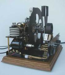
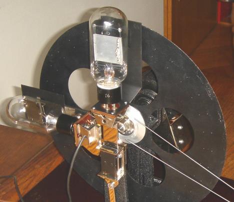
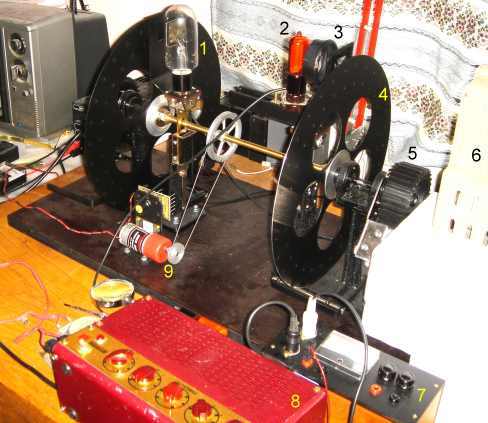
Kemudian piringan metal kecil berputar dengan lubang-lubang didalamnya ditemukan oleh seorang mahasiswa yang bernama Paul Nipkow di Berlin, Jerman pada tahun 1884 dan disebut sebagai cikal bakal lahirnya televisi. Sekitar tahun 1920 John Logie Baird dan Charles Francis Jenkins menggunakan piringan karya Paul Nipkow untuk menciptakan suatu sistem dalam penangkapan gambar, transmisi, serta penerimaannya. Mereka membuat seluruh sistem televisi ini berdasarkan sistem gerakan mekanik, baik dalam penyiaran maupun penerimaannya. Pada waktu itu belum ditemukan komponen listrik tabung hampa (Cathode Ray Tube)![]()
 Televisi elektronik agak tersendat perkembangannya pada tahun-tahun itu, lebih banyak disebabkan karena televisi mekanik lebih murah dan tahan banting. Bukan itu saja, tetapi juga sangat susah untuk mendapatkan dukungan finansial bagi riset TV elektronik ketika TV mekanik dianggap sudah mampu bekerja dengan sangat baiknya pada masa itu. Sampai akhirnya Vladimir Kosmo Zworykin dan Philo T. Farnsworth berhasil dengan TV elektroniknya. Dengan biaya yang murah dan hasil yang berjalan baik, orang-orang mulai melihat kemungkinan untuk
Vladimir Zworykin, yang merupakan salah satu dari beberapa pakar pada masa itu, mendapat bantuan dari David Sarnoff, Senior Vice President dari RCA (Radio Corporation of America). Sarnoff sudah banyak mencurahkan perhatian pada perkembangan TV mekanik, dan meramalkan TV elektronik akan mempunyai masa depan komersial yang lebih baik. Selain itu, Philo Farnsworth juga berhasil mendapatkan sponsor untuk mendukung idenya dan ikut berkompetisi dengan Vladimir.
TV ELEKTRONIK
Baik Farnsworth, maupun Zworykin, bekerja terpisah, dan keduanya berhasil dalam membuat kemajuan bagi TV secara komersial dengan biaya yang sangat terjangkau. Di tahun 1935, keduanya mulai memancarkan siaran dengan menggunakan sistem yang sepenuhnya elektronik. Kompetitor utama mereka adalah Baird Television, yang sudah terlebih dahulu melakukan siaran sejak 1928, dengan menggunakan sistem mekanik seluruhnya. Pada saat itu sangat sedikit orang yang mempunyai televisi, dan yang mereka punyai umumnya berkualitas seadanya. Pada masa itu ukuran layar TV hanya sekitar tiga sampai delapan inchi saja sehingga persaingan mekanik dan elektronik tidak begitu nyata, tetapi kompetisi itu ada disana.
TV RCA, Tipe TT5 1939, RCA dan Zworykin siap untuk program reguler televisinya, dan mereka mendemonstrasikan secara besar-besaran pada World Fair di New York. Antusias masyarakat yang begitu besar terhadap sistem elektronik ini, menyebabkan the National Television Standards Committee [NTSC], 1941, memutuskan sudah saatnya untuk menstandarisasikan sistem transmisi siaran televisi di Amerika. Lima bulan kemudian, seluruh stasiun televisi Amerika yang berjumlah 22 buah itu, sudah mengkonversikan sistemnya kedalam standard elektronik baru.
Pada tahun-tahun pertama, ketika sedang resesi ekonomi dunia, harga satu set televisi sangat mahal. Ketika harganya mulai turun, Amerika terlibat perang dunia ke dua. Setelah perang usai, televisi masuk dalam era emasnya. Sayangnya pada masa itu semua orang hanya dapat menyaksikannya dalam format warna hitam putih.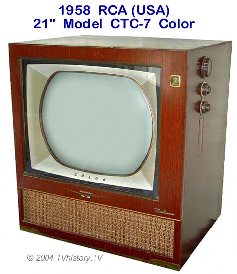
TV BERWARNA
Sebenarnya CBS sudah lebih dahulu membangun sistem warnanya beberapa tahun sebelum rivalnya, RCA. Tetapi sistem mereka tidak kompatibel dengan kebanyakan TV hitam putih diseluruh negara. CBS yang sudah mengeluarkan banyak sekali biaya untuk sistem warna mereka harus menyadari kenyataan bahwa pekerjaan mereka berakhir sia-sia. RCA yang belajar dari pengalaman CBS mulai membangun sistem warna menurut formatnya. Mereka dengan cepat membangun sistem warna yang mampu untuk diterima pada sistem warna dan sistem hitam putih. Setelah RCA memamerkan kemampuan sistem mereka, NTSC membakukannya untuk siaran komersial thn 1953.
Berpuluh tahun kemudian hingga awal milenium baru abad 21 ini, orang sudah biasa berbicara lewat telepon selular digital dan mengirim e-mail lewat jaringan komputer dunia, tetapi teknologi televisi pada intinya tetap sama. Tentu saja ada beberapa perkembangan seperti tata suara stereo dan warna yang lebih baik, tetapi tidak ada suatu lompatan besar yang mampu untuk menggoyang persepsi orang tentang televisi. Tetapi semuanya secara perlahan mulai berubah, televisi secara bertahap sudah memasuki era digital.


